Crankshaft Grinding Fundamentals
Crankshaft grinding is a complex, multi-step process that can include both cylindrical and surface grinding operations. What makes this type of grinding unique is that the grind itself plays a critical role in crankshaft performance.
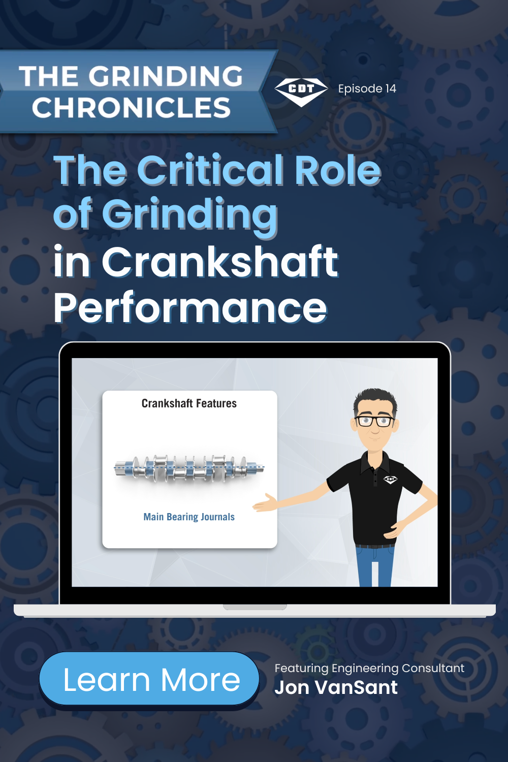
In this episode of The Grinding Chronicles, CDT Engineering Consultant Jon VanSant walks through the anatomy of a crankshaft and explains the grinding methods used to produce high-performance results. Watch the video or read on for a breakdown of the processes involved.
The Grinding Chronicles – Episode 14
The Critical Role of Grinding in Crankshaft Performance
In crankshaft manufacturing, grinding isn’t just another machining step — it’s where the final component takes shape.
The size, roundness, and surface finish are all set during grinding. The relationship between the different features of the crankshaft is also defined at this stage. Because the crankshaft is responsible for turning the up-and-down motion of the pistons into rotational motion, those elements have to work together accurately.
Unlike some components that can be adjusted later, a crankshaft depends on the precision achieved during grinding. The form and surface condition established in this process directly affect how the crankshaft runs in the engine.
That’s why crankshaft grinding is considered one of the more demanding precision grinding applications in automotive manufacturing.
Understanding the Anatomy of a Crankshaft
Before discussing the grinding process, it’s important to understand the features that make up a crankshaft.
At one end of the shaft is the post, where a pulley will be attached. At the other end is the flange, which mounts to the flywheel.
Along the shaft are two primary journal types:
Main bearing journals (Mains) are located along the centerline of the crankshaft. These journals support the crankshaft within the engine block. One of the mains includes thrust walls to limit axial motion.
Rod journals (Crankpin journals) are positioned at equal distances around the shaft. These journals convert rotational motion into the up-and-down movement that drives the pistons.
Each rod journal is paired with counterweights, which balance the rotating assembly and counteract the motion of the connecting rods.
Every one of these features requires precision grinding, and each presents unique challenges.
Grinding Methods for Rods and Mains
Depending on the machine tool and production strategy, rods and mains may be ground together or separately. Two common grinding approaches are full form plunge grinding and vector grinding.
Full Form Plunge Grinding
In full form plunge grinding, the grinding wheel is dressed to match the exact contour of the finished journal. The wheel plunges straight into the rotating crankshaft journal to its final depth, then retracts.
Because the wheel already contains the final form, this method can be efficient and repeatable in high-volume production environments.
Vector Grinding
Vector grinding uses a narrower grinding wheel to grind both rod and main journals, despite the fact that rod journals are typically wider.
Instead of plunging straight in, the wheel:
Moves down one side of the journal
Traverses across the surface
Interpolates the radius
Side-grinds on exit
This motion is more dynamic, with the machine interpolating angles and tracing radii almost like a lathe operation. The benefit is flexibility: you can grind multiple journal widths using a single wheel specification.
Grinding the Thrust Wall
The thrust wall—located on one of the main bearing journals—controls axial movement within the engine. Most thrust walls are plunge ground. However, in some cases, the machine may traverse and side-grind into the wall to achieve the final width. From a finished-part perspective, both approaches can achieve the same result. The difference lies in how the machine tool executes the motion:
Vector-style interpolation moves at angles while tracing the radius.
Side grinding feeds straight in using the side of the wheel.
Understanding the machine’s motion is essential when selecting the appropriate grinding wheel specification.
Post and Flange Grinding
Post and flange grinding are typically plunge operations performed with the wheel head oriented at a 30-degree angle to the shaft.
During this process, the wheel feeds in from the end of the crankshaft, grinding both the outer diameter (OD) and the face simultaneously. This combined OD and face grinding requires stability, precision, and proper wheel selection to maintain geometry and surface integrity.
Grinding Wheel Technology in Crankshaft Applications
Historically, crankshaft grinding was commonly performed using conventional aluminum oxide grinding wheels, and those wheels are still used in certain applications today.
However, much of the industry has transitioned to vitrified CBN grinding wheels for hardened steel crankshafts. Vitrified CBN wheels offer improved form retention and consistency, particularly in high-volume production where maintaining journal geometry is critical.
Regardless of whether a process uses conventional wheels or vitrified CBN wheels, both rely on rotary diamond dressers to maintain wheel profile and keep the grinding surface properly conditioned. Optimized dressing intervals ensure that the wheel continues to generate the required journal form throughout the production cycle.
Machine Footage Courtesy of Fives landis Corp.
This episode features crankshaft grinding footage from Fives Landis Corp., part of Fives Group’s Grinding | Ultra Precision business line. The video showcases operations on the Landis LT2e, Landis LT2HHe, and Landis 3LVe platforms.
We appreciate Fives for allowing us to include this footage and highlight these machines in action. If you’re interested in learning more about their grinding platforms and manufacturing solutions, you can visit their website at:
Optimizing Your Crankshaft Grinding Process
At CDT, we have extensive experience supporting crankshaft grinding applications—from wheel specification to process optimization. If you have questions about your current crankshaft grinding wheels or are looking to improve cycle time, wheel life, or part quality, our engineering team is here to help.
📧 Contact us at TheGrindingChronicles@cdtusa.net or visit cdtusa.net/the-grinding-chronicles for more insights into precision grinding.
🔔 Follow CDT on LinkedIn and YouTube for future episodes of The Grinding Chronicles and news on the latest in grinding technology.
-
Crankshaft grinding determines the final dimensions, alignment, and surface quality of the component. Since these factors directly influence engine performance and durability, achieving precision during this stage is essential for proper operation.
-
Full form plunge grinding uses a wheel shaped to the final contour and feeds directly into the workpiece, making it ideal for high-volume production. Vector grinding, on the other hand, uses a narrower wheel with complex movements to handle multiple journal sizes, offering greater flexibility.
-
Main journals support the crankshaft within the engine block and maintain its rotation, while rod journals connect to the pistons and convert rotational motion into linear motion. Both require precise grinding for smooth engine performance.
-
While traditional aluminum oxide wheels are still used in some cases, vitrified CBN grinding wheels are widely preferred for hardened steel crankshafts due to their superior consistency, durability, and ability to maintain form over long production runs.
-
Efficiency can be improved by selecting the right grinding method, optimizing wheel specifications, and maintaining proper dressing intervals. These factors help enhance cycle times, extend wheel life, and ensure consistent part quality.
